Using a variety of y and k factor bend allowance calculations designers can create flat patterns of the designs.
Bend sheet metal creo.
This is a simplified version so i can t use forms or punches.
Mathematically k factor is a ratio of position of neutral axis and sheet thickness.
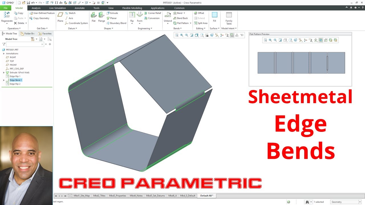
Now that you have a sheet metal part just go to the edit bend command.
When the tangent to bend depth option is used in a relation the relation is maintained but the result produced will be the.
Ptc was quite proud of it.
Click edit bend in the mini toolbar.
Creo sheet metal training.
Get to know them better to learn advance concept easily.
Start by selecting the bend surface.
What is k factor in sheet metal fabrication.
If i had to i would add the tongue after the bend feature.
You can substitute a bend table for the y factor if you so desire.
0 kudos reply.
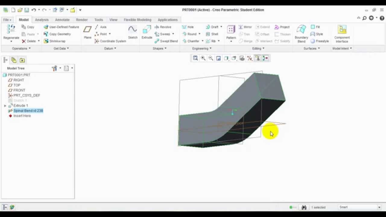
So what i did was build the extrude converted it to sheet metal driving surface and then added a bend feature selecting one of the end edges as the bend line the bend radius would be change from thickness to whatever diameter you are wrapping the label on to.
As sheet metal parts are flattened or formed if you start with a flat state pro sheetmetal utilizes a y factor to allow for the fact that metal is elastic and stretches as it bends.
When you open legacy models created in creo parametric release 4 0 and previous releases in creo parametric 5 0 the tangent to bend depth option is replace by the on origin depth option.
Sheet metal modeling and drawing with bend table.
Creo sheet metal tutorial sheet metal bracket 1 in creo parametric duration.
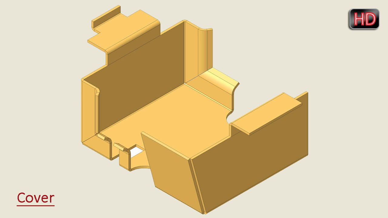
What is the method to create sheet metal bend that has a flat area as shown since bend line in sketch must be one entity.
This comprehensive suite of creo sheet metal design tools helps users create features such as walls bends punches notches forms and relief features.
I thought they added something for this in creo 3 0.
Bend line shift bls the distance from the outside mold line to the original bend line on the flat pattern this is used to calculate the backstop location when working off of a flat pattern.
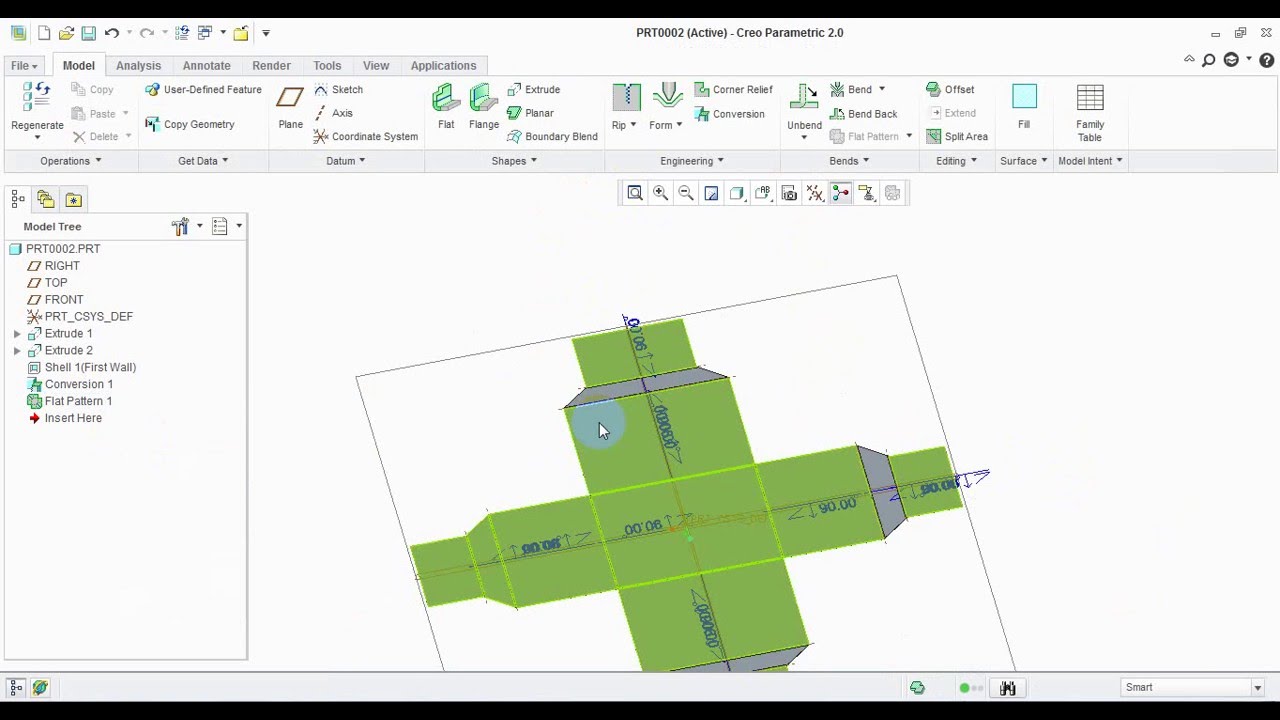
See convert a solid part into a sheet metal part for details.
Value of k factor is always less than 0 5.
Here end the fabrication formulas for sheet metal up next we ll be seeing some of the terminologies in sheet metal that you ll need.
From creo parametric 5 0 release the depth option tangent to bend in not available.